رقم العضوية : 9523 تاريخ التسجيل : 23 - 9 - 2008 الجنس : ~ الاهلي المشاركات : 155,340 الحكمة المفضلة : Canada SMS : Male
دعوه لانشاء مصنع صغير لتصميم وصنع الكترونيات itor Monitoring System with Raspberry Pi and Pi Camera
By
Saddam 0 Comments Raspberry Pi is an ARM cortex based popular development board designed for Electronic Engineers and Hobbyists. With the processing speed and memory, Raspberry Pi can be used for performing different functions at a time, like a normal PC, and hence it is called Mini Computer in your palm. We have created a series of Raspberry Pi tutorials , to start with Raspberry Pi from scratch and then create high level
IoT projects using Raspberry Pi.
This time we are here with our next interesting project which is
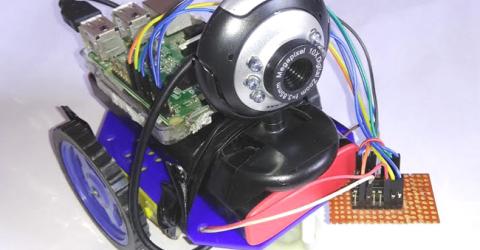
Visitors Monitoring System with Image capture functionality . Here we are
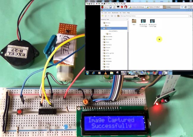
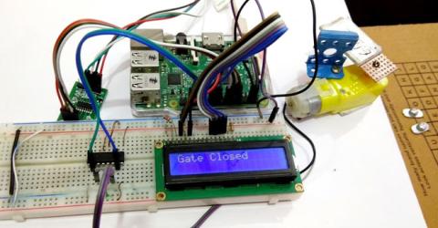
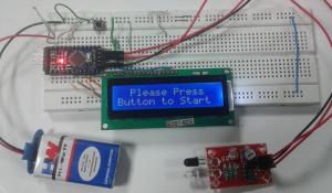
interfacing Pi camera with Raspberry Pi to capture the image of every visitor which has entered through the Gate or door. In this project, whenever any person is arrived at the Gate, he has to press a button to open the Gate, and as soon as he/she press the button, his/her
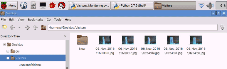
picture will be captured and saved in the system with the Date and time of the entry . This can be very useful for
security and surveillance purpose.
This system is very useful in offices or factories where visitor entry record is maintained for visitors and attendance record is maintained for employees. This Monitoring system will digitize and automate the whole visitor entries and attendances, and there will be no need to maintain them manually. This system can be either operated by the person himself or there can be operator for pressing the button for very visitor. This is a good project for
getting started with Pi camera and interface it with Raspberry Pi .
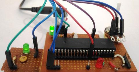
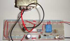
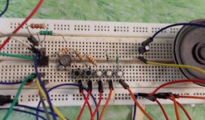
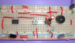
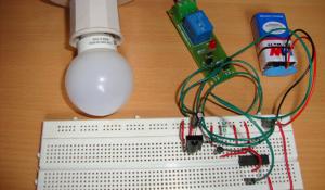
Components Required: Raspberry Pi Pi camera 16x2 LCD DC Motor IC L293D Buzzer LED Bread Board Resistor (1k,10k) Capacitor (100nF) Push Button Connecting wires 10k Pot Power supply Working Explanation: Raspberry Pi Monitoring System is simple. In this, a Pi camera is used to capture the images of visitors, when a push button is pressed or triggered. A DC motor is used as a gate . Whenever anyone wants to enter in the place then he/she needs to push the button. After pushing the button, Raspberry Pi sends command to Pi Camera to click the picture and save it. After it, the gate is opened for a while and then gets closed again. The buzzer is used to generate sound when button pressed and LED is used for indicating that Raspberry Pi is ready to accept Push Button press, means when LED is ON, system is ready for operation.Video at the end.Circuit Explanation: Raspberry Pi Visitor Surveillance System is very simple. Here a Liquid Crystal Display (LCD) is used for displaying Time/Date of visitor entry and some other messages. LCD is connected to Raspberry Pi in 4-bit mode. Pins of LCD namely RS, EN, D4, D5, D6, and D7 are connected to Raspberry Pi GPIO pin number 18, 23, 24, 16, 20 and 21.
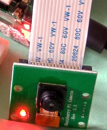
Pi camera module is connected at camera slot of the Raspberry Pi. A buzzer is connected to GPIO pin 26 of Raspberry Pi for indication purpose. LED is connected to GPIO pin 5 through a 1k resistor and
a push button is connected to GPIO pin 19 with respect to ground, to trigger the camera and open the Gate.
DC motor (as Gate) is connected with Raspberry Pi GPIO pin 17 and 27 through
Motor Driver IC (L293D). Rest of connections are shown in circuit diagram.
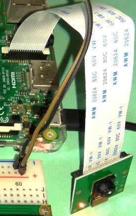
To connect the Pi Camera, insert the Ribbon cable of Pi Camera into camera slot, slightly pull up the tabs of the connector at RPi board and insert the Ribbon cable into the slot, then gently push down the tabs again to fix the ribbon cable.
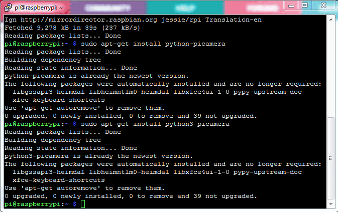
Raspberry Pi Configuration and Programming Explanation: Python language here for the Program. Before coding, user needs to configure Raspberry Pi. You should below two tutorials for Getting Started with Raspberry Pi and Installing & Configuring Raspbian Jessie OS in Pi:install Pi camera library files for run this project in Raspberry pi. To do this we need to follow given commands:enable Raspberry Pi Camera by using Raspberry Pi Software Configuration Tool (raspi-config):Enable camera and Enable it.reboot Raspberry Pi , by issuing sudo reboot , so that new setting can take. Now your Pi camera is ready to use.def capture_image() is created to capture the image of visitor with time and date.def gate() is written for driving the DC motor which is used as a Gate here.def begin() function is used to initialize LCD, def lcdcmd(ch) function is used for sending command to LCD, def lcdwrite(ch) function is used for sending data to LCD and def lcdprint(Str) function is used to send data string to LCD. You can check all these functions in Code given afterwards.continuously read the Push button using while loop. Whenever the push button is pressed, to open the gate for entry, image of the visitor is captured and saved at the Raspberry pi with date & time and gate gets opened. Check the Full code and Demonstration Video below.Camera Monitoring System has lot of scope to upgrade, like a software can be built in Computer Vision or in OpenCV to match the captured picture of visitor with the already stored images and only authorized the visitor if some match has been found, this will only open the gate for authorised people.EasyEDA for Circuit Design and PCB Prototype
Try EasyEDA: A Free and Easy-to-Use PCB Design Tool for Every Engineer Prototype PCB: Only $8.21 for 10 pcs, 2-Layer 100x100mm PCBs, 2-3 days delivery Leave a comment
Your name *
E-mail * The ******* of this field is kept private and will not be shown publicly.
Subject
Comment *
More information about **** formats No HTML ***s allowed. *** page addresses and e-mail addresses turn into links automatically. Lines and paragraphs break automatically. Related ******* DIY *** Controlled Raspberry Pi Surveillance Robotic Car IoT Raspberry Pi Smart Container with Email ***** and *** Monitoring Voice Typing on 16x2 LCD using Raspberry Pi and Android App How to Find IP Address of Raspberry Pi using Python ****** Raspberry Pi Based Weight Sensing Automatic Gate Latest Posts Active forum topics More User login
E-mail or username *
Password *
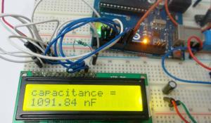
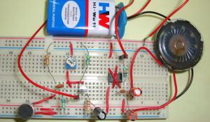
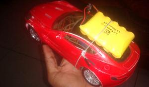
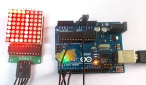
Ask Question Featured Projects and Circuits Smoke Detector using MQ2 Gas Sensor and Arduino Arduino Robotic Arm [IMG]https://circuitdigest.com/sites/default/files/styles/medium_sc_350x200_/public/projectimage_mic/Raspberry-Pi-Home-Security-System-with-Email-*****.jpg?itok=qe1NTfCY[/IMG] IOT based Raspberry Pi Home Security System with Email ***** DIY Smart Vacuum Cleaning Robot using Arduino Smart Phone Controlled FM Radio using Arduino and Processing How to Use NeoPixel LED Strip with Arduino and TFT LCD Call and Message using Arduino and GSM Module Arduino Based Digital Clock with Alarm Live Temperature and Humidity Monitoring over Internet using Arduino and ThingSpeak Capacitance Meter using Arduino Arduino based Vehicle Tracker using GPS and GSM LED VU Meter using LM3914 and LM358 Simple Audio Amplifier using 555 Timer IC Bluetooth Controlled Toy Car using Arduino 8x8 LED Matrix using Arduino Emergency Light DIY Piano IR Based Security Alarm Tachometer using Arduino Remote Controlled Light Switch View all Featured Projects
Sign Up for Latest News
Popular Topics: Robotics Projects |
Arduino Uno Projects |
Electronics Projects |
555 Timer Circuits |
ATmega32 Projects |
ATmega8 Projects |
Raspberry Pi Projects |
IoT Projects
Copyright © 2017
Circuit Digest . All rights reserved
Privacy policy |
Disclaimer |
Contact Us |
Submit |
Advertise شمس الحب
]u,i ghkahx lwku wydv gjwldl ,wku hg;jv,kdhj
آخــر مواضيعـى » رواية بنات اون لاين كاملة,تحميل رواية بنات اون لاين,رواية سعودية جريئة,على ملف وورد موسوعة الروايات,تحميل روايات في ملف وورد ومفكرة, أكثر من 100 رواية مشهورة تحميل روايات كاملة على هيئة ملف وورد او مفكرة تكست txt تحميل روايات فارس احلامي,الحب المستحيل,بشروه اني ابرحل,سعوديات في بريطانيا,احلى ماخلق قمر خالد كاملة,قمر خالد للتحميل,قمر خالد على ملف وورد,قمر خالد رواية,رواية قمر خالد
التوقيع


 المواضيع المتشابهه


 Visitor Monitoring System with Raspberry Pi and Pi Camera
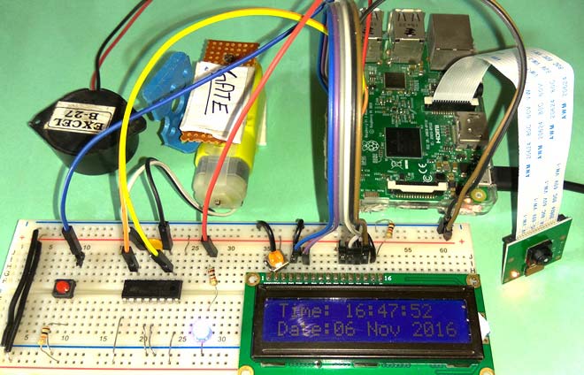


 العرض الشجري

